Someone is having a great time with their T4!

7 Likes

Very nice pic marutks!
Also - thanks to lost33 for providing such a nice review for the T4! We think it’s a great amp, of course, but it’s nice to see others responding that way, too.
8 Likes
@TomB
Welcome Tom!!
Please feel at home here!
Some folks will probably have some questions for you about the T4. I can honestly say even though I have several other amps (12) that the T4 is one of the very best amps I have ever heard…its absolutley superb with Focals and other headphones. Definitely a TOTL amp.
Alex
6 Likes
The T4 is on my current top 2 amps I want to try/buy! Glad you are here on the forum! Looking forward to seeing your insights!
5 Likes
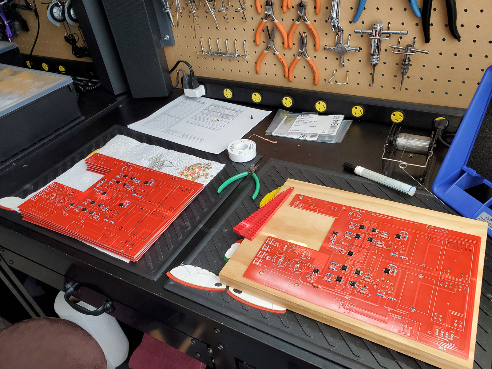
Six T4 headphone amplifiers nearing completion:

The PCBs are complete; casework is next. Included in the scene is one of several COVID-19 masks that my wife has sewn lately - just so you all know that this is current.
If you will allow, I have some pics coming up next that detail the unique construction and parts that go into the ECP Audio/Beezar T4.
8 Likes
Thanks for the update Tom!
Hope some of the folks here take advantage of this amp, its indeed AWESOME!
Alex
2 Likes
Uhh… If you don’t share those pics I will be mightily disappointed!
![]()
3 Likes
Thanks, Alex!
I hope you and your family are doing OK during this corona virus stuff.
5 Likes
Sorry - mistaken post!
2 Likes
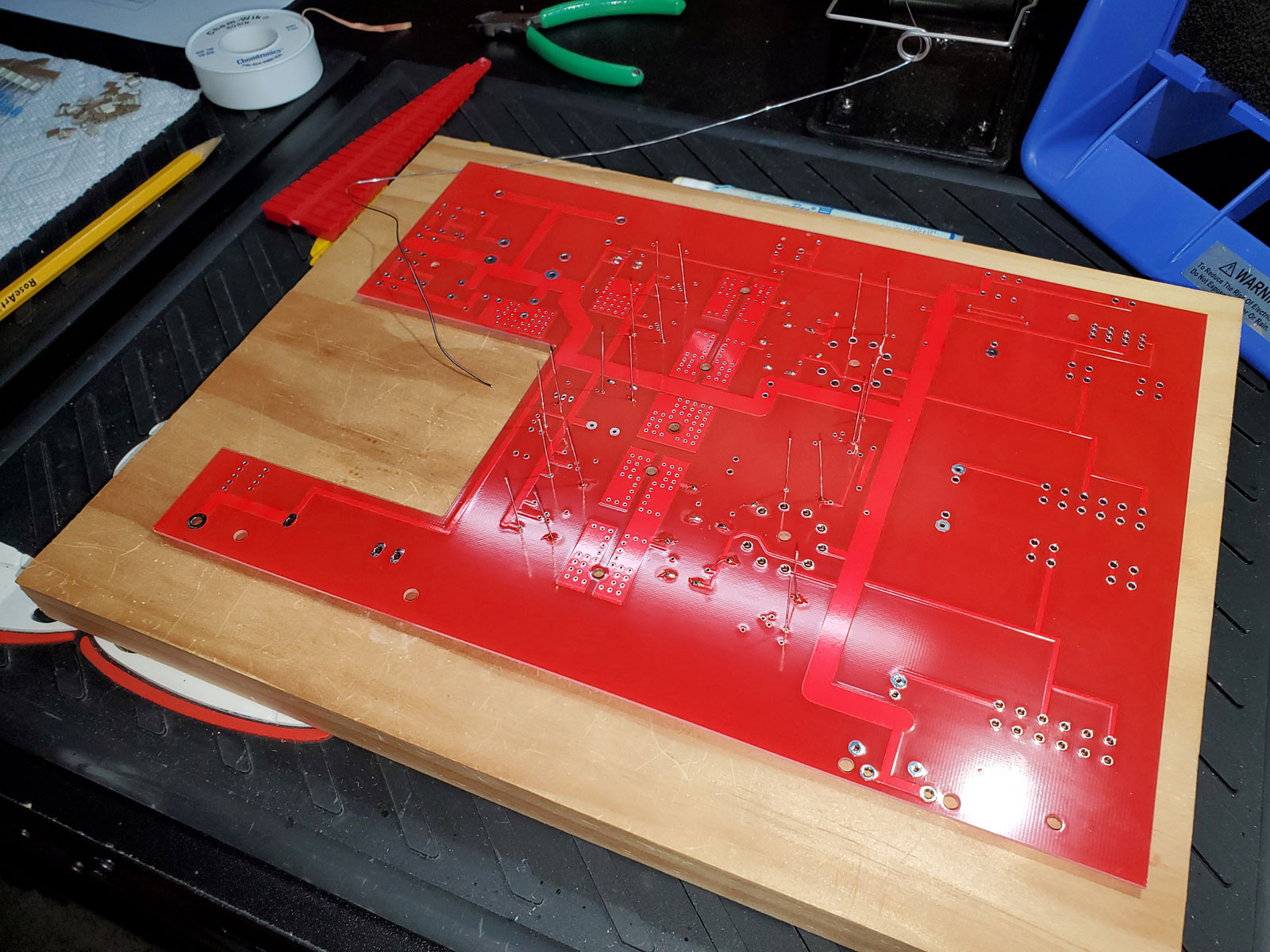
Here’s the PCB bottom:

Here you can see those heat-sinking planes duplicated on the bottom of the PCB, with the vias connecting from top to bottom. The other notable item is the complete absence of a ground plane. Usually, with most headphone amplifier designs that use a PCB, one surface of the PCB is used for the circuit traces and the other side is used for a ground plane that covers most of the area of the PCB. With the fully differential circuit beginning at the tubes and continuing to the output transformers, a common ground plane is impossible. However, there are many supporting parts of the circuit - power supply, tube heater supply, CCS circuits, and connectors - that utilize a common ground. That’s the large trace pointed out above and the branches that follow.
5 Likes
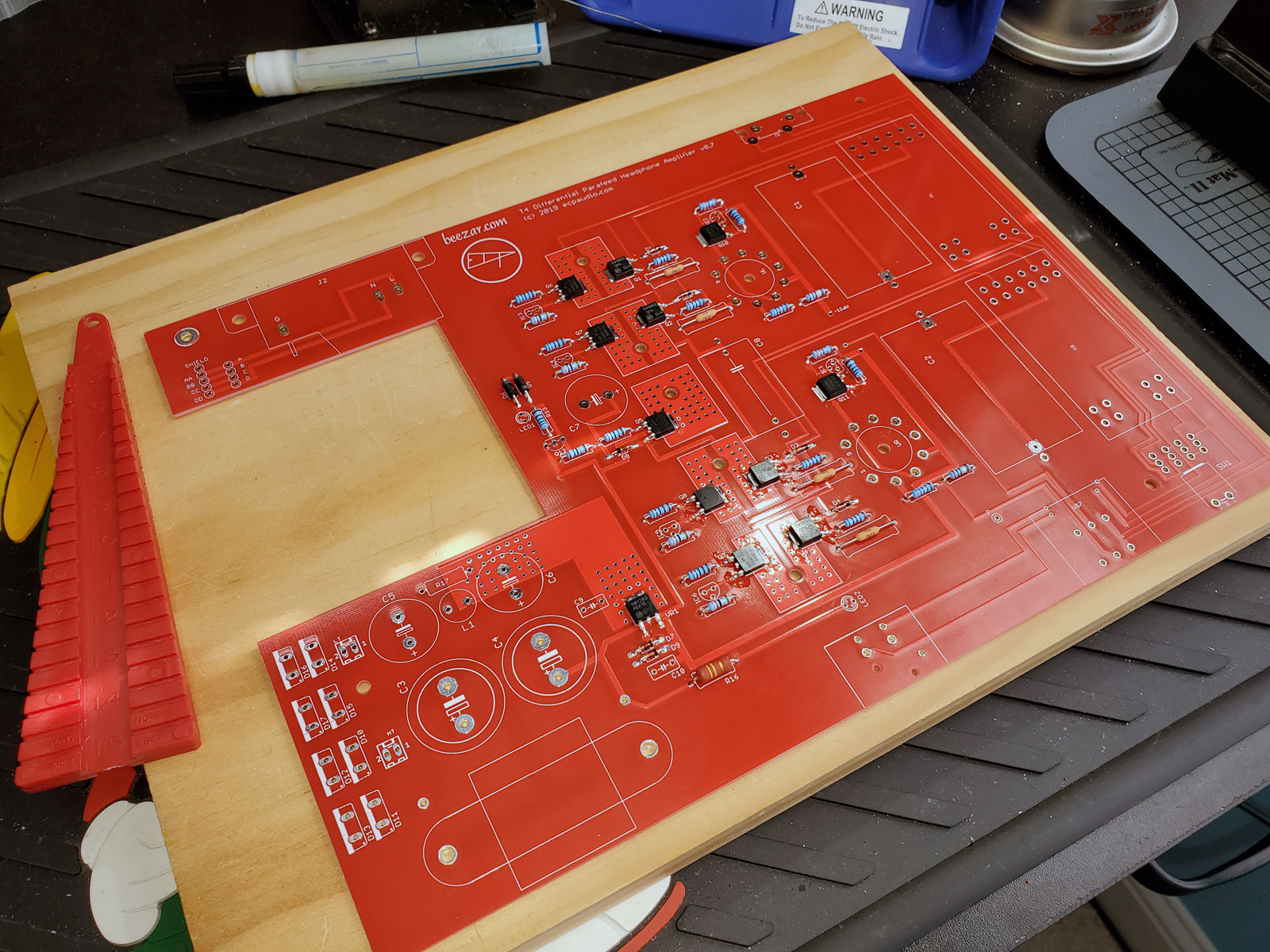
One of the first things to notice about the T4 design by dsavitsk are some unique features with the PCB:

The cutout for the Power Transformer is obvious, but this was done to avoid any cross-contamination of the 60Hz AC with the PCB. On other thing to notice about the top of the PCB (also on the bottom) are the heat sinking areas directly on the PCB. This is because the power transistors in the solid-state, fully differential buffer are SMD chips soldered directly to the PCB. However, despite the fact that they are small, SMD chips, they build up as much heat as many TO-220 transistors. You’ll see later on how the heat transfer goes together, but there is a very thick, aluminum “heat bar” that is bolted to the bottom of the PCB and to the bottom of the casework. It attaches directly to these rectangular pads with ceramic insulators in-between. The ceramic insulators are needed, because there’s close to 300V that pass through these pads. The numerous vias are used to fully integrate the sinking planes from the top of the PCB to the bottom of the PCB. Fairly unique, but it allows complete heat sinking through the entire casework, instead of bulky and somewhat inefficient (by comparison) PCB-mounted aluminum heat sinks.
7 Likes
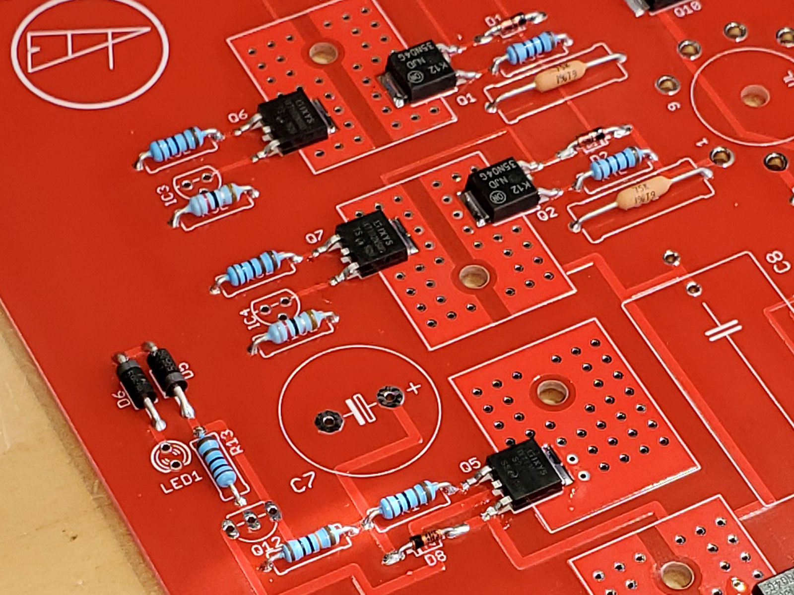
The first step in populating the PCB begins with the lowest height part and ends with the tallest part. On the T4, that begins with the small diodes, followed by the tube plate resistors:
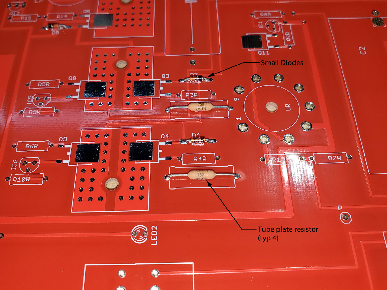
The small diodes are straightforward, you just need to make certain that the polarity is correct. As for the plate resistors, shown here as the large, reddish-tan, 75K resistors, there’s a story behind those .
During the T4 predecessor amplifier design by dsavitsk of ECP Audio, the Torpedo III (or T3, for short), there was quite a discussion on another forum about the plate resistors. Of course, back then the T3 was DIY and everyone was trying their own flavors of parts. Some worked, some didn’t. Anyway, this particular builder noted that the plate resistors in a tube amplifier have an effect on the sound quality. He was absolutely right about that, but just not in his particular suggestion.
Dsavitsk and I had originally used standard, higher-wattage metal film resistors in the T3 as the plate resistors, but this builder wanted to try the boutique Amtrans carbon-film resistors. They come with a unique construction and reputation that can be found on PartsConnexion here: https://www.partsconnexion.com/media/pdfs/Amtrans_amrg.pdf.
After quite a bit of hoopla over them, I tried them … but didn’t like them. They actually dulled the response in the highs, making the details of cymbal hits disappear in a fog. So, I dismissed the idea of changing the plate resistors from the metal films.
Until … many months later a customer sent me a T3 for repair and asked me to install a different style of resistor at the plate resistor positions: the Texas Components Corporation TX2575 resistors. These were “naked” bulk metal foil resistors, now owned by Vishay (what electronic part isn’t owned by them anymore?). Again PartsConnexion carries them under the new brand of Vishay here: https://www.partsconnexion.com/VISHAY-80844.html.
When I installed them in the customer’s T3 … Wow! They really made a difference: highs were cleaner and even more detailed than with the standard metal films. Unfortunately, as you can see in that PartsConnexion link, they are quite unorthodox and expensive, at almost $14 each. That was $56 for a single amp!
That said, when dsavitsk designed the T4, I mentioned the TCC/Vishay resistors to him. His answer was the type of resistor shown in the pic above. It has very similar qualities, but in a more orthodox construction, availability, and price. Apparently dsavitsk did a lot of his own research and tried out different resistors before finding these. They are still expensive at $3-$4 each, but worth every penny on this amp. Please understand that differences such as these often go unnoticed in a typical amplifier. With the T4 and even the T3 before it, every little increase in part quality yields positive results, because the amplifier performance is at that level.
The actual resistors used in the T4 can be found here: https://www.mouser.com/datasheet/2/427/cpf-1762878.pdf. They make a difference and are very little different in performance from the TX2575 resistors described above. Here’s a pic in mid assembly, with the plate resistors’ leads bent and ready to insert in the PCB:
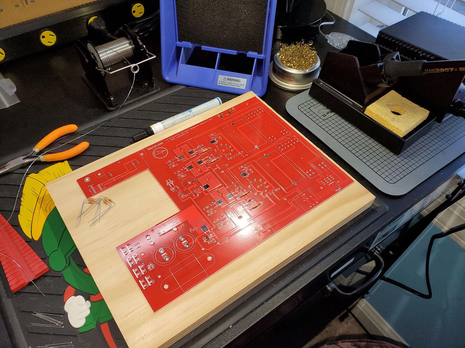
By the way, that little red triangle lead-bending tool on the left is worth its weight in gold, especially when assembling several amplifiers such as this, with varying lead lengths from part to part.
(I’ll try to be less verbose and have more pics on following posts.)
7 Likes
Tom,
That’s an awesome post! I hope this is a full build log kind of article you’re doing for the T4?
Also, SMD soldering is the devil. Just my take on it.
Thank you!
3 Likes
Yes - that’s the intent. Thanks for the question! Apparently, with the forum rules here, I needed someone else to post before I could post again. 
4 Likes
Speaking about SMD, next up are the SMD transistors, voltage regulators and MOSFETs. No big deal here, except that the assembly is typical SMD: liquid flux in a tube, small solder, small soldering iron tip, and tweezers to hold the parts. (I assemble a lot of DACs, too, and believe me - this is simple in comparison!)
Standard SMD soldering technique:
- Apply solder to a single pad at each part position.
- Re-melt the solder with the soldering iron in one hand, while at the same time, holding the part with tweezers in your left.
- Use the tweezer to move the SMD part into position, into the molten solder.
- Remove the soldering iron while still holding the part with the tweezers.
- Let everything cool, remove the tweezers and solder the other leads/etc. of the SMD part.
The tabs are particularly important here. One needs to be certain that the transistors are flat on the heat sink pad and that the transistor tab is soldered completely flush with a clean joint. Otherwise, you lose heat sinking capability.

A closeup (tabs on right have not been soldered yet):

6 Likes
I’ll keep posting then!
It’s a little different, this forum platform. I think restrictions ease after you do a few posts. Anti-bot spamming kind of prevention, probably.
4 Likes
Ahh … this is the very, very boring part of populating a PCB - the rest of the resistors:
You can see the PCB flipped over here, so that I can solder all of the leads:
It’s a lot of work and you don’t really get a sense of having accomplished a lot, once completed. It’s absolutely necessary, though, and probably because of my complaint - is often where focus is lost and the resistors get mixed up, causing untold grief in trying to troubleshoot once the amp is built. I keep all the resistors in their labeled bags and insert only one value in their proper positions at a time, to remove the chances of those errors.
Once again, dsavitsk surprised me. I actually replaced his basic resistors in the T4 prototype with the familiar Vishay-Dale brown sausage-like resistors. The V-D resistors have been used by DIY-ers for at least 20 years, now. They are absolutely consistent in quality and manufacture and as metal films, are light years ahead of the old carbon comp resistors. They’re hard to beat.
I had a small flirtation with PRP resistors, sold at PartsConnexion and many other places as a colorful (they’re red) V-D replacement. Some people were excited about them around 10 years ago. I even had a line on a local distributor that was going to supply me in bulk with these. Unfortunately, when trying them I found that they were inconsistent: sometimes they were “blobs” instead of “sausages,” and the red epoxy shell seemed to break and fragment very easily. You have to almost use a pair of pliers on a V-D resistor to break one. So, I was back to the dependable V-D resistors quickly.
So, I asked dsavitsk about the T4 - “Why do you keep using these cheap, colorful foreign resistors?” “Because they’re better,” he tells me. “Whaaaat?” I said. Sure enough, he got me again:
https://www.mouser.com/datasheet/2/427/mbxsma-1286643.pdf
Turns out they are German and started in Berlin as Beyschlag. Their power rating is better than the V-D RN55 resistors, so is their tolerance, and they’re smaller. So, I switched, too:
Another shot while in the middle of resistor work:
7 Likes
Thanks Tom!
We are fine, just bored as all heck!!
Keeping busy with several things here…music is one of them!!
Stay Safe on your end as well and many thanks for the updates on your awesome T4!
Alex
3 Likes
This is awesome. I love hearing about the thought process that goes into these things. Makes you appreciate it all even more.
3 Likes