The T4 amp is the best amplifier I have had the pleasure to test and use for several days here at the homefront…
I have several other amps, all good, some really good but the T4 is at the top of the list for sure…
Alex
The T4 amp is the best amplifier I have had the pleasure to test and use for several days here at the homefront…
I have several other amps, all good, some really good but the T4 is at the top of the list for sure…
Alex
Thankfully, things start going faster (or at least the feeling that you’re accomplishing something) after the TO-92 transistors. The first of the large parts, the tube sockets are next. With a tube amp, it’s important to have the standoffs very, very close to the tube sockets. Or, better yet - directly under each tube socket. This is because the act of plugging a tube into a socket puts a lot of stress on the socket and the PCB. If it’s not properly supported, bad things can happen.
Once again, Doug spec’d an improvement in tube sockets:
https://s3.amazonaws.com/tubedepot-…ached_files/00004280-VT9-ST-C1.pdf?1383248764
The Belton socket has a couple of advantages as a PCB-pin tube socket:
With #1, you get high-temperature structural stability, along with vibration resistance. You don’t get any vibration resistance with a typical ceramic socket. Old NOS sockets made out of bakelite are not exactly vibration-resistant.
With vibration resistance, you minimize microphonics. Every tube is probably microphonic to some degree, simply from the mechanical construction involved. So even if it’s not audible, it might be measurable and have an otherwise non-localized affect on the sound quality that could be audible.
With #2, every instance I’ve measured and tested where the lead lengths were increased on tubes, either from socket protectors, flying leads, or what-have-you, the longer signal path causes measurable increases in noise. So, low profile is good from that perspective.
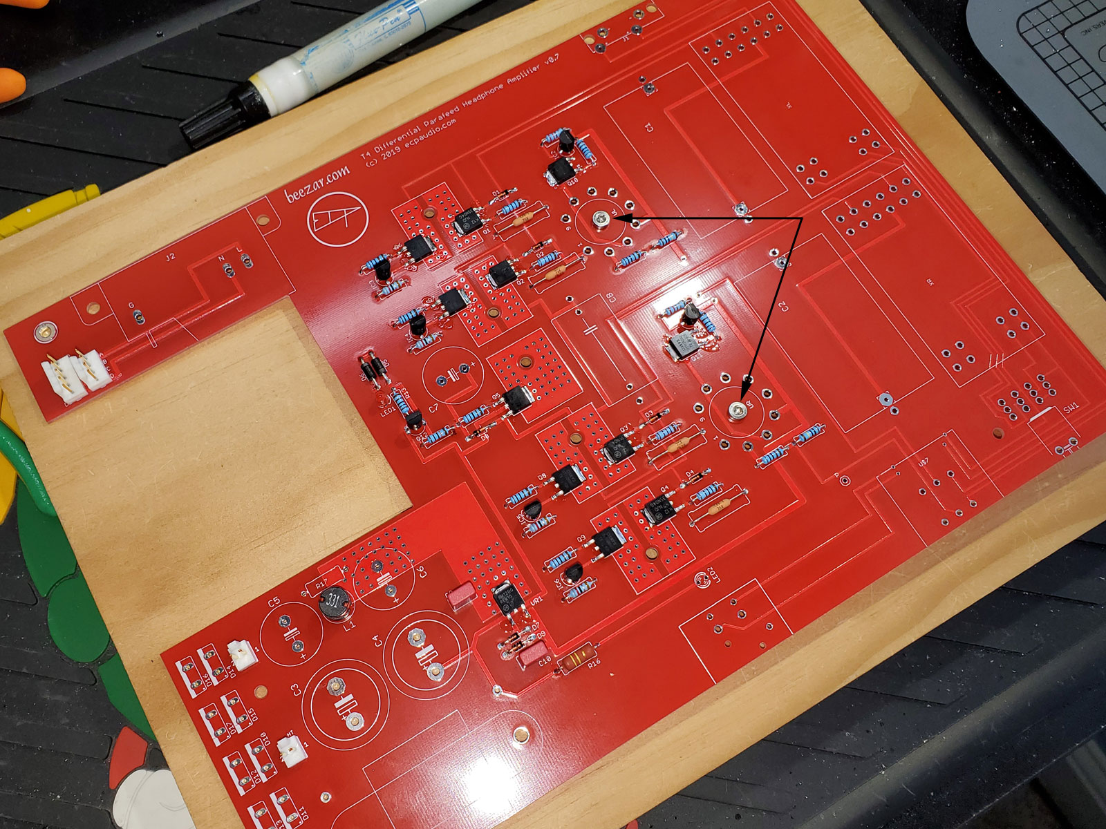
From the perspective of using standoffs, low profile is bad. It means the standoff mounting screws below are captured by the tube sockets. IOW, if you don’t put the screws in first - before soldering the tube sockets in place - you’re in a world of hurt. I won’t tell you what I went through with the first few T4s when I forgot this. 
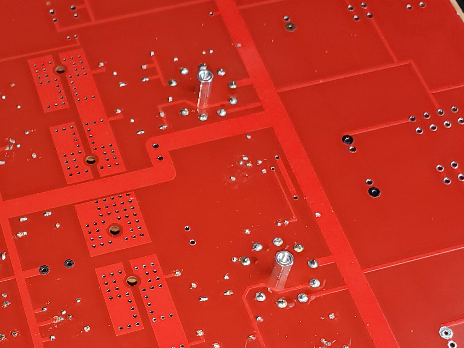
So with those screws highlighted above, here’s a shot of the standoffs underneath the PCB:
And with the soldering done:
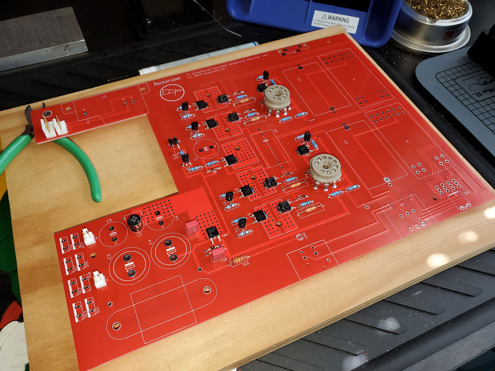
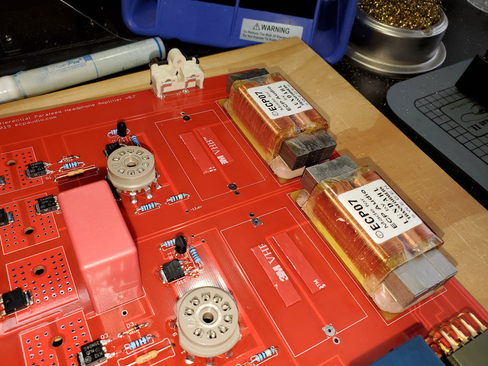
Top view of the sockets, along with the Molex plug-ins for the power transformer, the power inductor, and film filter caps also installed:
As you can see, there is a center hole in the sockets, so one is always able to tighten, loosen and remove the standoff. However, the screw stays secure under the socket, trapped by the socket pins.
Because the sockets undergo so much stress, I am careful to ensure that solder flows up the pin legs from the pads below. This ensures maximum strength with the socket’s attachment to the PCB.
During all of this, I’m able to stack the PCBs to save space while working on them:
As you can see, I’ve installed the Z-switch. At 4-pole, double-throw, it means 12 pins to solder for each switch! 
Next up are the rectifiers, 4 for the tubes’ B+ supply, and 4 for the tube heaters power supply. These are irritating to me. In a TO-220 form with only two leads each, they will shift not only backwards and forwards, but side-to-side as well. So, I solder one pin each with as best alignment as I can then flip over the PCB to check the alignment. Some creative bending is performed as necessary, then the PCB is flipped over and the remaining leads soldered:
I do four at a time, to ensure that I don’t mix up the high-voltage rectifiers (tube B+) with the low-voltage ones (heaters). It helps that one set are completely rectangular, while the others have chamfered corners on top.
I can not attest to the importance of this!!
Any movement of the tube socket pins from removing a tube over time will cause fractures in the soldering of devices to the socket tabs…I have had this happen to several DIY amps and one amp inparticular from a very good vendor.
If discrete devices are not strain relieved properly the devices can mechanicaly fail and cause bad thing to happen. Been there done that.
Tube amp that have tube sockets soldered into the PCB prevent this pin wiggle movement and prevent these issues from happening!
In reviewing tube amps I make a big deal out of this, because its really important!
Nice job here Tom!
Alex
The wonderful Lundahl output transformers are next. From AtomicBob’s extensive tests, the Lundahls result in the following output impedances for the T4:
HiZ: 26 ohms
LoZ: 6.3 ohms
I believe these are unheard-of values for a tube output-transformer amplifier, especially that one at LoZ, 6.3 ohms.
Mandatory use of the exhaust fan is needed, because the heat from the soldering iron definitely causes the lacquer to smoke. The lacquer around the windings stays untouched, thankfully, but I believe they probably immerse the entire transformer in the lacquer, which means it’s on the pins and all around. So soldering the pins adds lacquer smoke to the solder flux smoke. It also causes the joints to dull. So, when you look at the bottom of a finished PCB, it may seem that the pins on the output transformers are cold joints - but they’re not! That is the melted lacquer preventing the solder from having a shiny appearance.
The Lundahls are a different size and shape than either Edcor or Cinemag PCB-mounted transformers, which we used in the past on both the Torpedo I and Torpedo III. The Edcors and Cinemags were square steel, with plastic runners underneath that held the PCB pins. Here’s a pic of one on the Edcor website:
In addition to dsavitsk’s implementation of a tube-parafeed design, and his proprietary DSHA-fully differential circuit, these Lundahls are a large part of the heart of the T4.
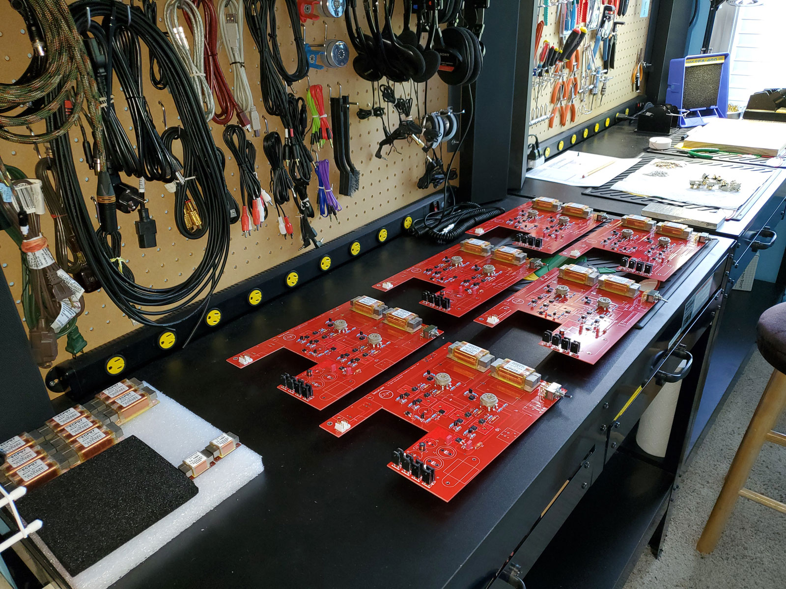
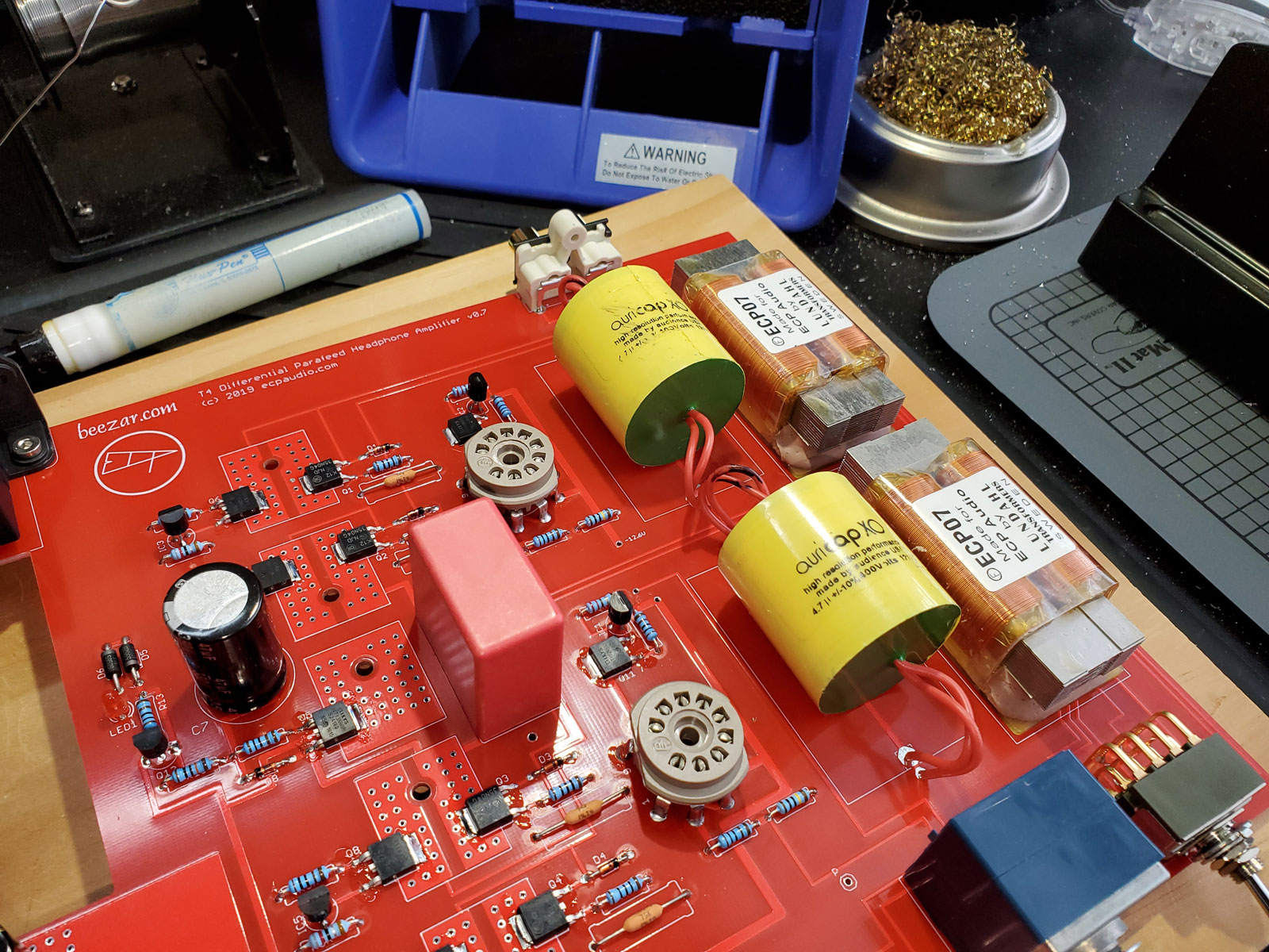
Here are pics in a steady progression of installation to the six PCBs under construction. You’ll note the stock of Lundahls at the left in the last pic:
The two tiniest Lundahls on the white foam are used as line-level outputs on the ECP Audio Walnut DAC.
Note that I can no longer stack the PCBs while working on them. The pins from the Lundahls on top will pierce the plastic wrap on the Lundahls underneath.
I can not attest to the importance of this!!
Any movement of the tube socket pins from removing a tube over time will cause fractures in the soldering of devices to the socket tabs…I have had this happen to several DIY amps and one amp inparticular from a very good vendor.
If discrete devices are not strain relieved properly the devices can mechanicaly fail and cause bad thing to happen. Been there done that.
Tube amp that have tube sockets soldered into the PCB prevent this pin wiggle movement and prevent these issues from happening!
In reviewing tube amps I make a big deal out of this, because its really important!
Nice job here Tom!
Alex
Ditto Alex! I absolutely agree with this!
@TomB you’re not helping my desire for one of these!
Ha!
You only live once!! Go for it!!
:>)
Things start going fairly fast, now. At least the parts are bigger, so it looks like more is being accomplished. Here you see the boards where I’ve installed the RCA jacks, heater power supply caps, and the Alps “Blue Velvet” RK27 volume pot. The RCA jack assembly is simple, with two plastic prongs that hook into holes on the PCB. They don’t move after that. You only need to solder the signal and ground leads. The two electrolytic caps for the tube heater power supply are similar - just two leads, each. However, I take great care that they are soldered flush to the board. You would not believe how common it is with commercial electronics, including supposedly high-fidelity equipment, where electrolytic capacitors are soldered in all sorts of alignments, lead lengths, bent leads, etc. - everything but simply straight and flush to the PCB. I think a lot of high-fidelity equipment might all test about 10% better if greater care was taken with how electrolytic caps are soldered.
Anyway, with higher quality Panasonic FM capacitors such as these, it’s actually the rubber plug that ends up being flush with the board. So, that’s also a built-in vibration isolator. As with some of the other parts, I solder one lead each on the caps, flip the PCB over to check alignment, then solder the remaining lead.
I buy the Alps Blue Velvet stereo volume pots directly from Alps in Japan. The 50K version is best for headphone amplifiers, but it’s not a standard stocked production model. So, any request for a 50K Alps must be a custom manufacturing run from the factory in Japan. I last purchased 400 of them from Alps soon after the horrible tsunami years ago. The Alps factory was hit by the tsunami, so they wanted 400 as a minimum order, instead of the previous 200 minimum. With that many pots, I still have a few dozen left today. Maybe in a sense, Beezar Audio contributed a tiny bit to Japan’s reconstruction after the tsunami. 
Anyway … the pots are difficult to solder, not because of anything having to do with the six pins, but because alignment is absolutely critical. They’re also somewhat top-heavy. All of the pins are concentrated at the front and the weight of the shaft wants to make it topple off of the PCB. So, it’s not so straightforward to get soldered in straight. Once you marry up the front plate and the giant machined-aluminum knob we use, it’s too late to correct any tiny misalignment. I guess I should use a protractor mounted on the shaft or something like that, but there’s no guarantee the PCB itself is aligned during soldering. So, I eyeball it - but very, very carefully. There is a scale square drawn on the PCB for the pot and it provides a great guide for alignment in the azimuth. However, alignment in the vertical is just as important. I solder the opposite back and front pins, then heat and cool the solder joints repeatedly while adjusting both the horizontal and vertical alignment. Once I’m happy it’s flush and straight, then I solder the remaining pins. It takes a while for each pot, but is very important.
To the left, you can see the XLR jacks are next to be soldered. Here they are soldered in place:
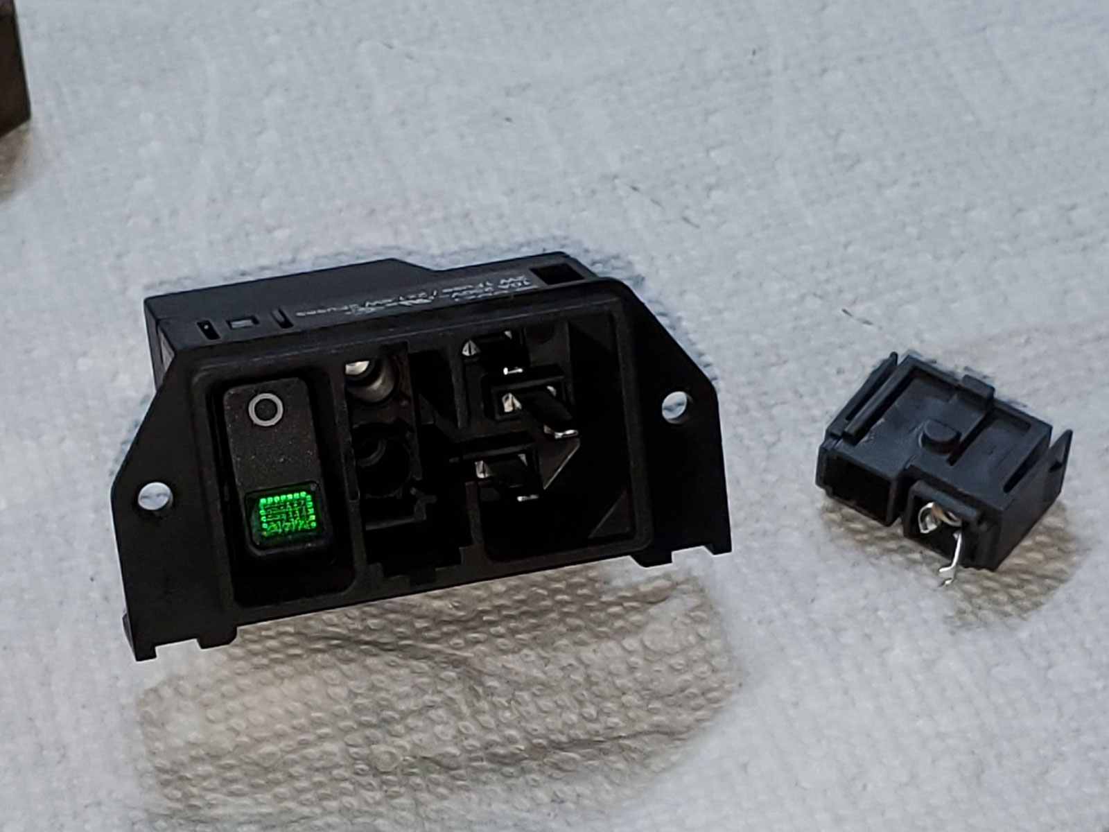
The choke (comes last) and the IEC inlet require both a mechanical connection and a soldered connection. The IEC inlet is up next:
Also part of the IEC inlet assembly is the power switch (lighted in this case) and a fuse box. The fuse holder is shown at right. The fuse only makes contact with the metal tab and the single socket at top inside the middle of the IEC inlet. The rest of the space is intended as storage for a spare fuse.
Back in the day with the original Torpedo I and Torpedo III, I once thought it was a neat idea to serve my customers well by supplying a spare fuse in that storage pocket. Unfortunately, not actually making an electrical connection with a tab and a spring, it would rattle if you moved the amp around. So, I had customers pulling out a brand new amplifier from the shipping box, hearing it rattle, and immediately thinking the amp was broken in shipment.  No good deed goes unpunished. This caused me so much grief from customers that I quickly stopped including a spare fuse.
In the T4, I have a little tool kit with screwdriver and spudger tool that I include, so it’s simple to include a spare fuse there, too.
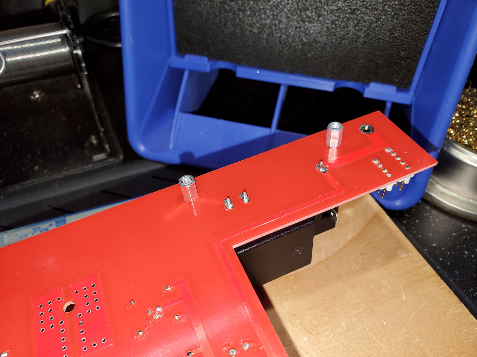
So, the IEC inlet is bolted in first. There is some play in the soldering connections and dsavitsk actually designs the case bottom with slotted holes for the IEC inlet. However, I’ve found it good enough to simply ensure that the IEC inlet is moved back away from the edge of the PCB as much as possible. The screws and standoffs are tightened down, then the leads are soldered into place. Here’s a view from the bottom with the IEC bolted into place (with standoffs), and its three leads (main, neutral, and ground) soldered in place:
Tom,
How many of the T4’s are available for sale??
Alex
Hey Tom,
Is there any chance you can put any information about the original Mullard tubes that were included?
I think many here would like the sound of those. Might make it easier to track it down if we knew what we were hunting for.
Tom,
How many of the T4’s are available for sale??
Alex
There are two reserved in this batch of 6 being finished up now. So, 4 are available.
Hey Tom,
Is there any chance you can put any information about the original Mullard tubes that were included?
I think many here would like the sound of those. Might make it easier to track it down if we knew what we were hunting for.
The Mullards are actually CV4024 tubes (12AT7 equivalent), most of which were manufactured in the 1980s. They are available from several different ebay dealers. This one I’ve bought from and seems reputable:
Just to be clear, Beezar Audio practices safety practices constantly. I have limited my trips to the Post Office to twice weekly and they are practicing social distancing with shields in front of the clerks and masks for everyone. UPS and FedEx is a much different matter, with very little interaction with the clerks involved … and no lines to speak of in the FedEx/UPS stores.
All of my parts come directly from Mouser or DigiKey,* with the following exceptions:
The Alps pots, as mentioned previously, date back to the Japanese tsunami.
The Z-switch is of Japanese origin, from the very high-quality, NKK company.
The XLR connector is Neutrik (German), but it may be manufactured in East Europe, I’m not sure.
Tube Sockets are Belton. Korean, I believe, and ordered from Tube Depot before the first production T4 was ever built.
The casework is all locally contracted, fabricated and anodized in the Atlanta suburbs. Wood is provided directly by Doug Savitsky from local sourcing.
The Lundahls are Swedish and come by way of K&K Audio in North Carolina.
The power transformers are manufactured by SumR in Canada.
The Audience Auricap XO parafeed capacitors (up next) come from California, but were purchased back in November.
The PCBs come from Taiwan, I believe (through Doug), but they predated the COVID-19 outbreak by about six months. Plus, they will all undergo a multiple 91% alcohol rinse to remove solder flux.
All hardware was purchased through McMaster-Carr, mostly in 2018.
Solid state chips and rectifiers are all reputable mfrs - TI, IXYS, Vishay, and ON. Some may have been outsourced to China, but the act of soldering surely exposes them to more than enough heat.
The Shurter IEC inlet is made in Czechoslovakia.
Resistors, as previously noted, are Vishay - mostly from Germany.
The LED for lighting the ECP Audio logo is definitely Chinese mainland, but date back to 2017 and earlier (many back to 2009).
I think that covers it, but if anyone has any other questions about the part sourcing, please ask and I’ll try to find out.
Up next are the parafeed capacitors, almost the last thing in populating the PCB before the choke and a couple of other capacitors.
Doug has written a great tutorial on headphone parafeed amplifiers here:
My level of understanding doesn’t approach his, but I’ll give it a try. If I state something incorrectly, hopefully Doug will correct it.
The output transformers in a parafeed arrangement are basically AC-coupled. There is a giant reason for this: safety. Doug has tried in the past to DC-couple the output transformers through the use of a servo. Unlike other servos you’ve perhaps seen in the SOHA II (Cavalli design) or Cavalli-Kan-Kumisa (another Cavalli mod), the servo that Doug has tried to make work runs at the high voltage of the amp. In the SOHA II, the tube was powered separately from the solid-state buffer circuit. The buffer circuit simply used a typical solid-state voltage supply at +or- 15VDC. Doug has been attempting to use a servo with the full plate voltage of a 12AT7, around 250VDC. This is the voltage passing through the DSHA-differential buffer of the T4 and the T3 before it.
His experiments resulted in the T5 a few years ago, but he could never lick the audible oscillation that would develop in the servo. This is all to zero out the DC offset, of course. Without that, the output transformer cores will saturate and bad, bad things can result if that happens. From what little I understand, it would mean the output transformer would basically change into nothing more than a resistance on the end of the 250VDC, exposing you and your headphone to that voltage, besides arcing and perhaps burning up the output transformers.
So … the parafeed arrangement with the output transformers use couple capacitors to block all DC offset ahead of the transformers. This is largely steady-state circuit offset. In normal turn-on and turn-off modes, the output transformers completely insulate the output from any voltage spikes.
So, the parafeed capacitors are extremely important to the circuit and even though the transformers are the real output, the capacitors are directly in the signal path. Good quality capacitors are thus very important.
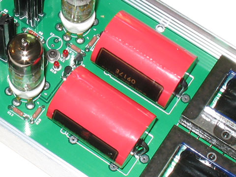
We have used many, many different kinds of parafeed capacitors in the history of the Torpedo. The Torpedo I initially used Clarity SA capacitors shown here:
Since the original Torpedo was DIY, builders used a variety of caps.
Epcos:

Cornell-Dubliers (CDEs):

The one above was actually built by Dr. Kevin Gilmore (more on the CDEs later).
When the Torpedo III came along, it was the first Torpedo or “T” amp to use the DSHA-differential buffer circuit. With the nickel-core Cinemags, it was more important than usual to protect the transformers from DC saturation, so the differential circuit needed four capacitors. We eventually - based on builder reports - used the Mundorf Silver-Oil EVO caps. These were very difficult to shoehorn into the existing design planform. They required a detailed lead-bending plan and custom insulating spacers that Doug designed. They also required a Dow-Corning adhesive (the white goo in the pic) to keep them from shifting in sh
ipment and use:Nevertheless, the Mundorfs had a “dry” sound signature that caused complaints from some. For some reason, 12AZ7 tubes seemed to counteract that the best, but they develop a lot more heat, which brought additional problems. CCS boards were added for the DHSA-differential buffer and for the tubes that complicated things even more. In addition, some 60Hz leakage from the power transformer was still showing up in testing. It was never enough to be audible, but was probably contributing to some false “warmth” that was never really there in the tube and Mundorf capacitors. Anyway, the problems with the tweaks and planform resulted in the T3 becoming way, way too difficult to build by the typical DIY-er (especially the inexperienced looking to save a quick buck). So, we quit selling them as kits and Doug focused on a future design.
The T4 was the result. Based on the previous experience above, Dsavitsk’s first prototype used the Mundorfs. When I got it, the amp sounded thin and lean. We suspected the Mundorfs and replaced them. Since Dr. Gilmore seemed to like the CDEs, that’s what I put in first. The amp sounded great!
It’s kind of interesting to see that the T4 amplifier has quite a heritage and can trace its lineage back many years through many versions, with improvements all along the way. 
Great posts Tom!
Alex
All along the way, dsavitsk kept suggesting the Audience Auricaps. I thought they were too expensive and that a hidden treasure could be found in cheaper caps such as the CDEs. Of course, I’m not a cut-and-dry objectivist, but I still have a developed prejudice against voodoo capacitors.
He convinced me try a set, though, and while were investigating other potential tweaks in the prototype, I purchased and received a couple of the Auricaps. Wow! Full body, more detail, superlative dynamics, etc. I was sold and claimed the Auricap XOs as standard from then on. Auricaps were not voodoo !
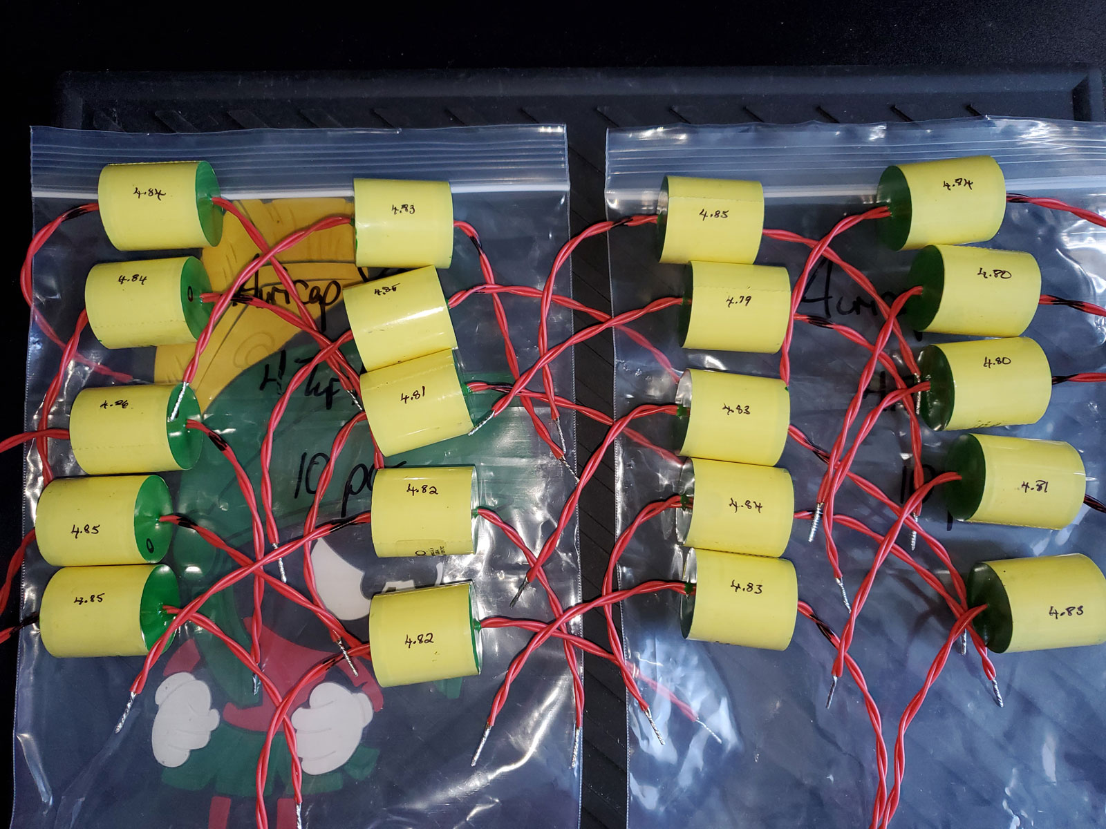
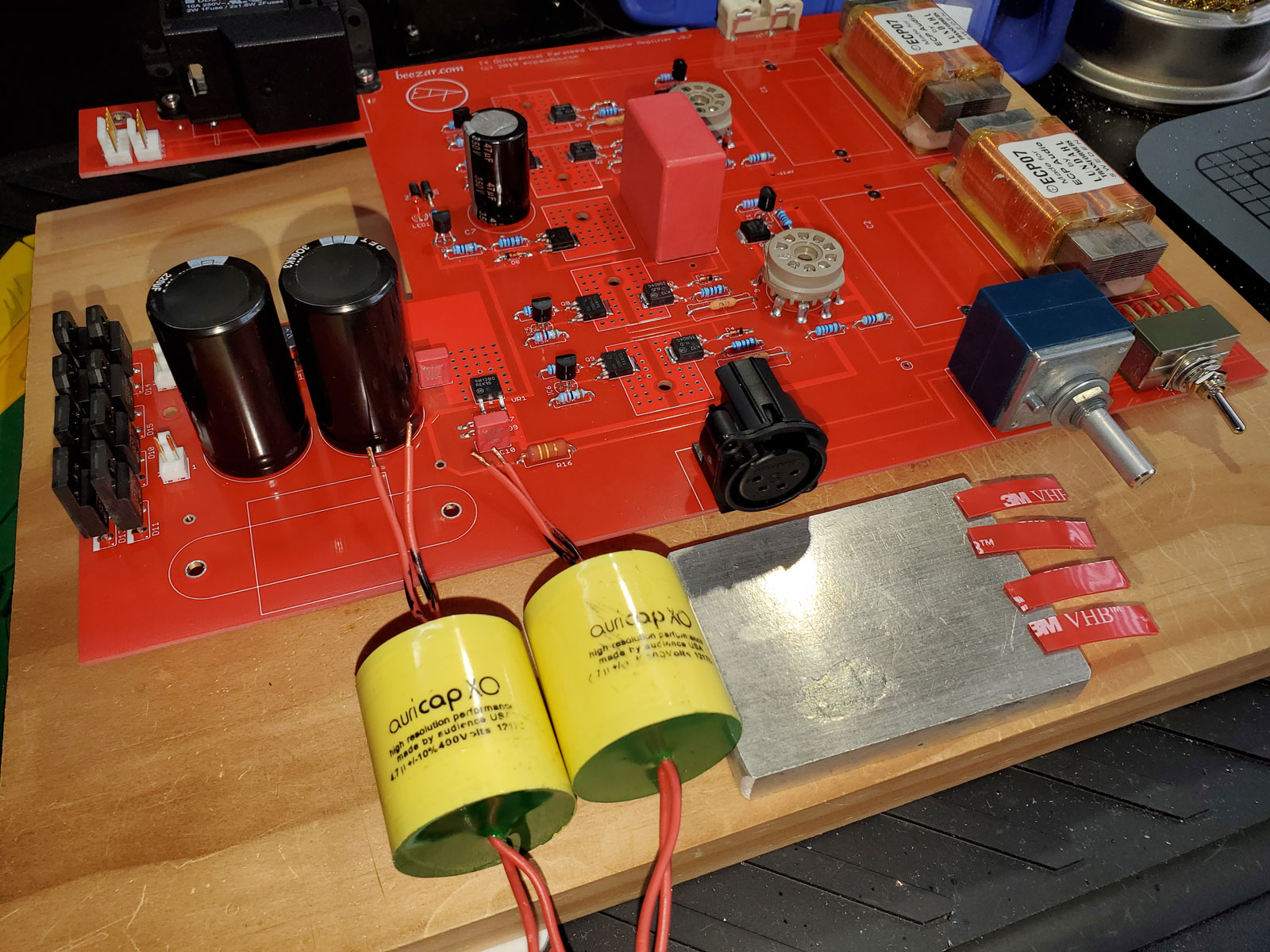
After messing around with the CDEs and then installing the Auricaps, I noticed that there were definitely differences in volume output, depending on the capacitor matching. It’s not as much as with mis-matched tubes, but it was still audible. So, I began with matching the capacitors in using Auricap XOs installed in the T4:
For this set of six T4s, I had ordered 20 Auricap XOs. Here they all are with measurements labeled on the bottom of the caps:
The Auricaps are different than most film caps in two ways:
They solder the double leads themselves from the factory, but leads on caps are always longer than needed. They are also longer than the minimum that causes trouble, so cutting them was no choice. It always scares me though, because you cut too much and you’re up the creek. I had long ago documented the proper length for the T4, however (with a generous safety factor).
Here’s a pair ready to be installed with the leads cut to proper length:
With caps this big and flexible leads (even if not), it takes more than just soldering them into place to keep them secure. To the right in the pic above, you can see four pieces of double-sided ultra-high-bond 3M tape. This stuff is clear, 2mm thick, and used in bonding materials in the aviation industry. So, it’s not trivial tape.
I use two pieces of tape per cap, placed lengthwise on opposite sides of the capacitor centerline on the PCB. After soldering them in place, I press down firmly on the cap, where the curvature touches the bare PCB right on the centerline, but is making contact with the tape on both sides of the centerline as in a saddle, so to speak.
This shot shows the tape in place at both capacitor positions, with the secondary film still in place on top of the tape:
And with the caps installed (double leads in separate pads and soldered separately):
The above is actually an improvement over this version of PCBs. After the first T4s were sold, I contacted Doug to order more. He asked if there were any changes that were needed. I told him we needed four pads for each parafeed capacitor, because of the Auricap double leads. In previous builds, I wrapped the stripped portion of one lead around the stripped portion of the other lead, leaving a knot of soldered lead above the PCB pads. Although functionally equivalent, it was an added hassle for me in building. This was a more straightforward improvement.
Not so simple for a capacitor install, is it? At least it is light-years simpler than those four Mundorfs in the T3.
One other improvement was made in this batch of PCBs - an extra mounting/standoff hole near the power rectifiers. You’ll see that in detail with posts about the casework assembly.
Excellent series you’ve done here. I don’t claim to understand everything you talk about as I I aren’t experienced in the ways that you are but it really goes to show the level of pride and excellence that go into these products.
The choke more or less completes the population of the PCB. There’s still an LED to add, but it stands proud and vertical to light the ECP Audio logo in the case top. So, I leave it last to protect from bending or knocking it off. Once the amp is assembled, it’s well-protected by the casework.
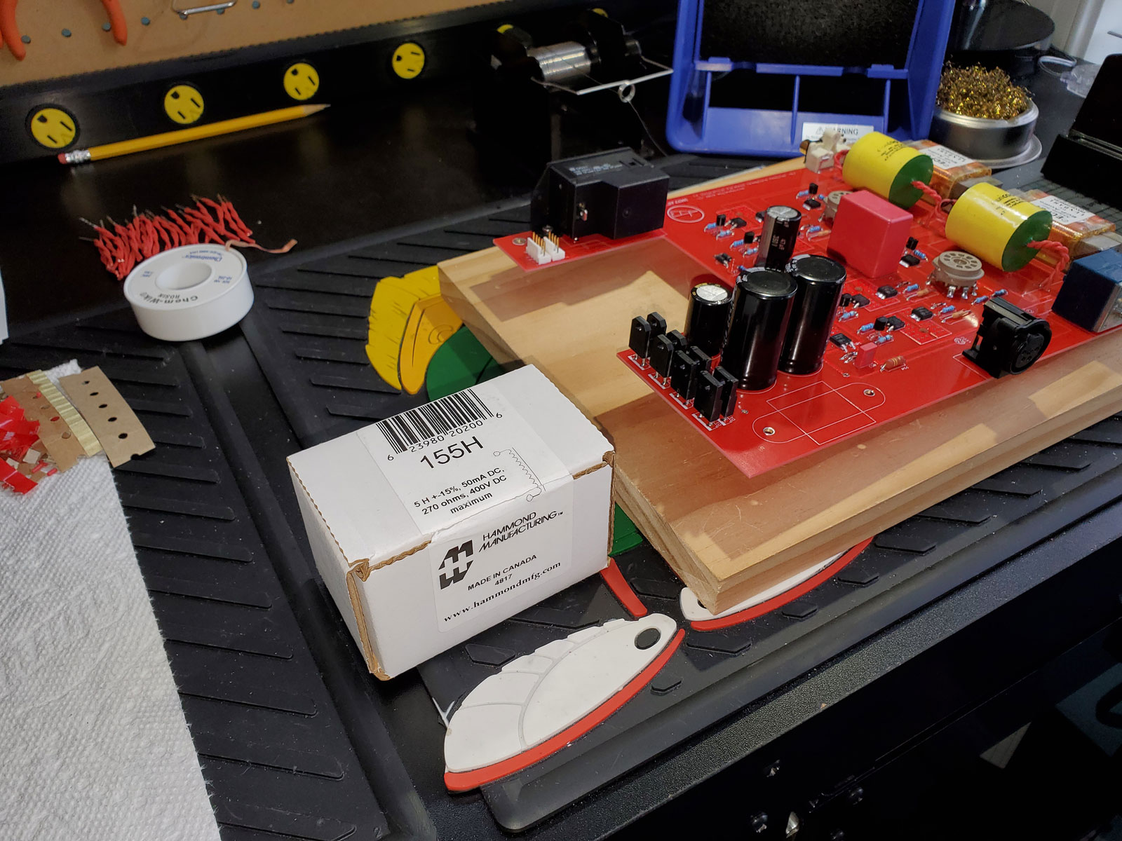
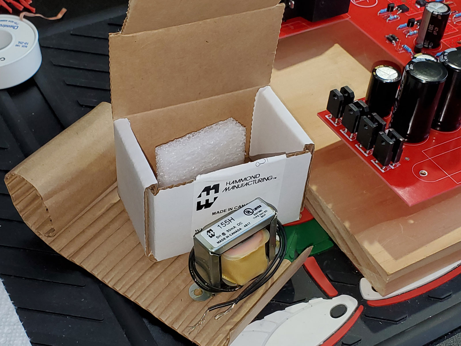
The chokes are made in Canada by Hammond Mfg. This is how they come from Mouser and elsewhere:
Opening the box:
The choke is a greater hassle in installation than it should be. Like the IEC inlet, it’s a combination of mechanical and electrical installation. That’s all steel there, so the choke is bolted to the PCB by the two tabs on the sides. Then there are two leads that are soldered into the PCB.
Unfortunately, that traditional bent-steel channel frame is very poor at dimensional control. The mounting tabs are rarely straight and parallel to the horizontal. The tolerance in the distance between those mounting holes is also very large. Finally, the lacquer used to seal the core (just like a transformer) appears to be applied after everything is assembled. There’s lacquer on the wire leads that breaks off when you flex them and there’s often lacquer covering the mounting holes and collected in the bend at the mounting tabs. You have to clean all of that out, or the mounting screws don’t fit, won’t go in at a vertical angle. Worse yet - if not cleaned, the lacquer can deteriorate over time or break off during shipping. That results in the screws coming loose and potentially having the choke come loose from the PCB!
When shipping the T4 prototype loaner from place to place, I once got it back after two or three shipping trips and found the choke held on by one screw and the remaining hardware rattling around inside the case! So, great care should be taken in removing the lacquer around the mounting holes, etc.
The tabs themselves, in addition to not being horizontal, are actually higher than the bottom of the choke. I’ve developed a practice of placing two washers between the tabs and the PCB so that everything is as orthogonal as I can get it.
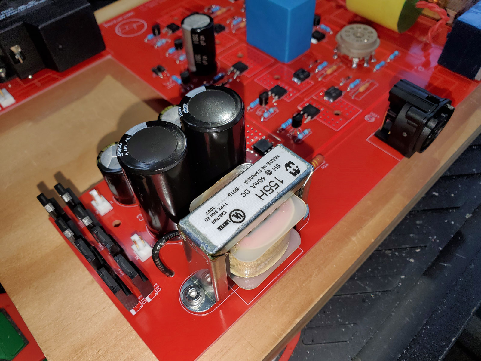
Here is the choke installed:
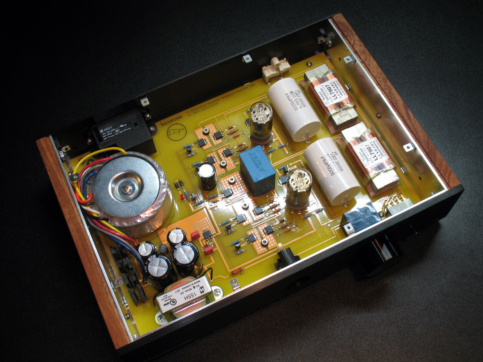
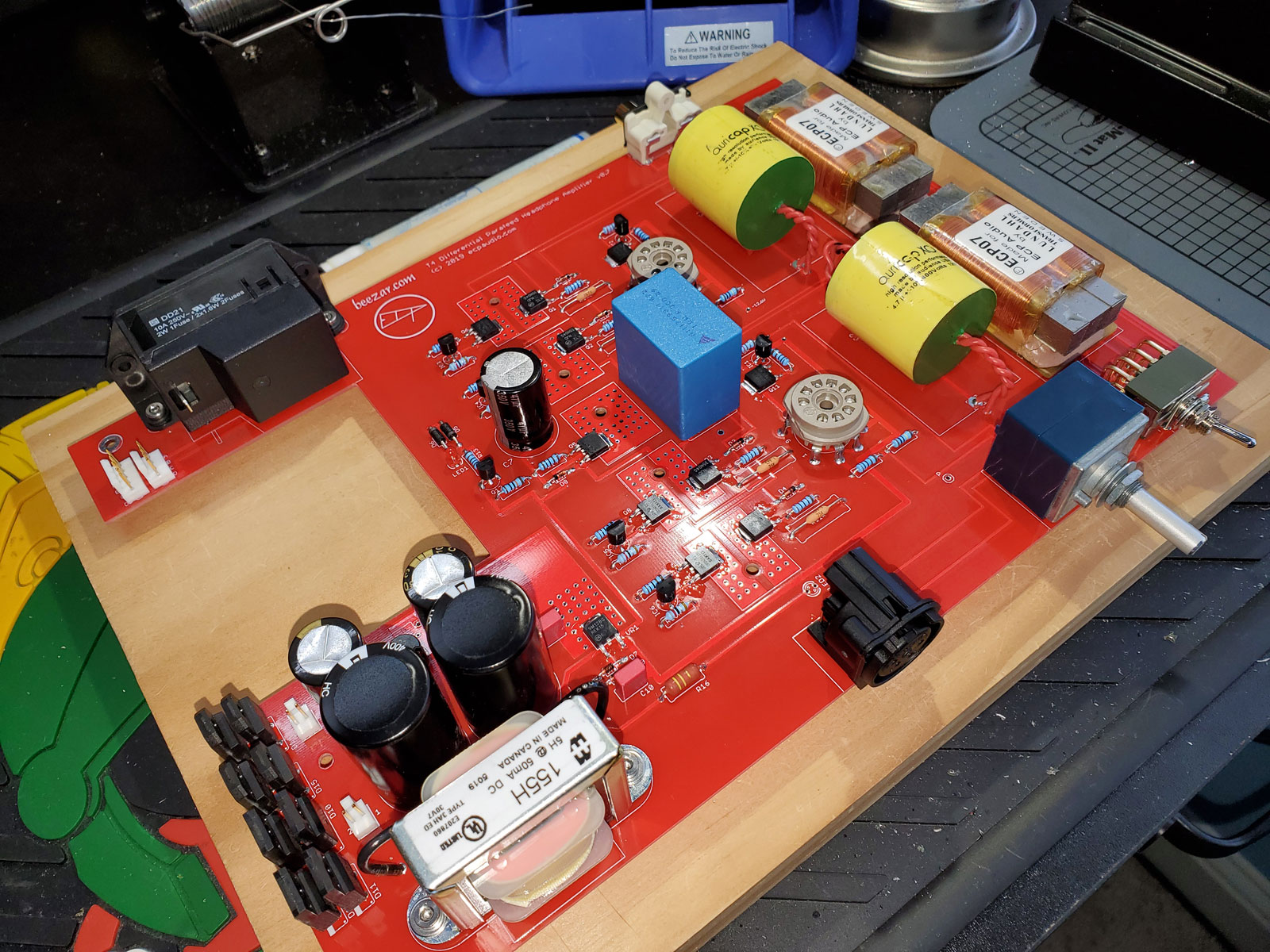
PCB finished and complete:
And, once again - all 6 PCBs populated:
Power transformers are next!