Now thats a beautiful site!!
:>)
Alex
Now thats a beautiful site!!
:>)
Alex
While I start work on the power transformers, I also start rinsing/cleaning the PCBs. I’m not sure anyone does this anymore, but I’ve been told that stray flux will corrode over time - or at least collect loads of dirt and stain - and eventually get so bad that it will conduct electrical current. So, I was always taught to clean up a soldering job.
Many people recommend flux - the more, the better. Generally, that is true, especially if you are soldering metal-to-metal for strength joints. I go way back (an old fart, now) and first started soldering to build brass slot car chassis in the late 60’s. I was still only a teenager. Back then, the order of the day was Kester rosin-core solder, with a hockey-puck sized tub of Kester soldering paste. Soldering irons for brass were best with an Ungar. You’d dip the end of the solder into the tub of flux, wait for the iron to melt/boil the flux paste on the end of the solder, then apply the solder. it worked well and was even fairly easy to clean up on the brass chassis that was built.
Electronics soldering is different. The parts are small and delicate. Too much flux and it becomes a nightmare to clean, and damaging parts becomes more likely. So, I like to use flux only when something gives me trouble soldering - or with SMD. I always use a flux pen with SMD. The flux quickly partially dries into almost a glue. So, it helps to stabilize the part while soldering. In a lot of cases, a full flush of alcohol works quite well, so cleanup is not so bad - even with the additional flux - in using SMD. Without leads, the parts are not so delicate. There are always exceptions, of course.
The solder I use is still Kester rosin-core, but is eutectic 63-37. The rosin core, 99 times out of 100, is sufficient flux to make a great joint. It still leaves quite a bit of flux residue, however.
So … I rinse and clean every PCB with alcohol. I do this until most, if not all, of the flux is removed and the PCB is nice and shiny. It’s not rocket science and very rudimentary, but I wouldn’t feel right selling an electronic product without doing it. The pic below shows the basic tools (very complicated!  ):
):
On the other side of the sink, the PCB is placed top down on a set of paper towels:
Looking at the pic below, you can see why this is necessary. The area around the tube sockets are worst, because of all the solder I use to make a good mechanical joint:
It generally takes about six rinses of alcohol, applied with the toothbrush by dipping into the butter tub, coating the PCB with the brush, and rubbing/brushing at the leads and pins where the flux collects. Then I pat up the dissolved alcohol/flux with paper towels, before the alcohol completely evaporates. As said, it’s far from rocket science and very tedious, but necessary.
I use the simple Walmart 91% alcohol because it works best. I purchased some commercial flux remover solution years ago, but just using a little almost knocked me out. It also didn’t remove the flux as well as simple alcohol. I’ve never used it since. Sometimes the alcohol fumes get strong, but TELs are quite high for alcohol and the coating is quite thin. I think it works the best.
Here’s what it looks like after the first rinse. One might think it’s not worth the trouble, because this looks ten times worse than before we started, with streaks and gunk everywhere:
This shows the paper towels absorbing the dissolved flux/alcohol rinse. When it’s thick, the paper towels will turn a yellow-brown where it picks up the mixture:
Believe it or not, this pic is very, very close to being completely clean. When it looks like this - dissolved white powder everywhere - it means that the hard, dried flux bubbles have all been dissolved and are drying as a fine rosin powder all over the PCB. From this point, it only takes about two more rinses:
Here is a PCB completely rinsed, nice and shiny:
Here’s a closeup of the tube socket area that we pictured above - big difference, now!
And the rinsed top of the PCB:
Thanks for your patience! I know this is not flashy stuff, but a necessary part of the building process.
The biggest question is where did you get that isopropyl alcohol, that’s like gold right now!!
In all honesty, I am just curious as to the amount of man hours it takes you to put this all together given your current level of experience and expertise?
At some point I’m going to restart this thread from the beginning and just lounge through it, I love it.
The biggest question is where did you get that isopropyl alcohol, that’s like gold right now!!
So true - I was going to write that it’s a unicorn right now, but I forgot. Needless to say, I had some stock on hand. ![]()
In all honesty, I am just curious as to the amount of man hours it takes you to put this all together given your current level of experience and expertise?
If I counted up the hours, I’d probably quit. Obviously, I am never making an adequate return on the work put in it.
It’s more like a belief in the unique designs that Doug Savitsky produces and the opportunity to be part of it. Do I hope to make money at the same time? Heck, yes! Doesn’t everyone? However, Doug’s designs are so unique and trailblazing, more people should notice them, especially the market. I think his stuff is as good as Pete Millett, Alex Cavalli (better than his), or Morgan Jones, etc. So, I toil in the hopes that one day, the market will explode for Doug’s designs.
In the meantime, I take comfort in the fact that the work and effort is worth the reward in the quality and performance of the amplifier (and hope to make a little money).
At some point I’m going to restart this thread from the beginning and just lounge through it, I love it.
Many thanks!
You do not make it easy for me to resist buying one of these… Really love this series you did! I love unique hand built passion items…Hence my love of ZMF =) I may have to re-arrange some budgets but I may have to put down for one of these if one is still available! What are the wood options?
Wood is Sapele Mahogany. I’ll have some pics later on when the casework assembly begins.
Meanwhile, work on the power transformers begins, while still rinsing the PCBs of flux residue. These are the very last steps prior to final assembly with the casework.
The power transformer connections and mains voltage setting all use the Molex KK254 terminal system. These are convenient crimp-on terminals with a dizzying array of housing and header offerings. Dsavitsk and I originally thought that we would be able to order the transformers with the headers already installed. Unfortunately, that did not turn out to be the case. So, the original prototype and loaner T4 were built with the power transformer leads soldered into place and the voltage setting jumpers were spent leads soldered into the PCB pads.
There were two issues with this:
With #1, this is a missed opportunity for convenience, because the power transformers are spec’d for 220V-110V windings and the IEC inlet allows the use of all types of domestic and international cords/plugs. However, if the actual voltage setting on the PCB requires soldering skills, this severely limits the options to the customer. So, if a US customer eventually wants to sell his/her amp to an international customer, soldering skills are necessary - even more, sufficient soldering skills to remove existing solder and jumpers.
With #2, there are a total of 9 leads from the power transformer that attach to the PCB. When assembling or disassembling, the fact that all the leads are soldered to the PCB, yet the transformer is bolted to the case bottom, means that assembly/disassembly is awkward at best, potentially damaging to the transformer at most.
So, once I started building T4s for sale (after the two prototypes), I started researching the Molex KK terminal system. Unfortunately, as noted above, I’ve never encountered any other parts system that is as widespread and confusing as the Molex. I eventually settled on the KK 254 terminal system, which seemed to be the proper choice for 22 gauge wiring and a 2.54mm pitch (pin spacing on PCB). I used the headers with friction locks, housings with both locking ramps and rib “wings.” All pins and crimp terminals are gold.
The next step was to acquire a crimper tool. Knowing that this would be used for hundreds of crimp processes, I wanted to get the best tool available. So, I started looking for the actual Molex-brand tool: about $350, everywhere I looked. Well, that ended that. So, I started searching elsewhere and finally settled on this IWISS tool from Amazon:
It’s Chinese and those handles are basically completely styrene, not mixed plastic with a gray rubber grip. However, the crimping die seemed of good quality and it got pretty good reviews, so I gave it a shot. It seems to be working OK, although you have to hold it upside down to use it properly. I have thought about removing the dies and re-installing them reversed, but I haven’t had the time to try that, yet.
Here’s a pic of other tools I used for the Molex terminal system:
Here’s a pic of all of the Molex KK254 system pieces that I purchased, organized in a Harbor Freight parts box:
And … here’s a pic of the SumR toroid power transformer used for the T4:
The transformer comes just as you see pictured, with two rubber mounting pads and a steel rubber clamp washer. No mounting bolt, nut, or washer/lock washer was included.
For perspective, here’s the entire arrangement laid out on one of my work tables:
The first step I’m going to do is to make more Molex shorting jumpers that are used to change the voltage setting. Here’s an excerpt from the T4 manual:


So, these jumpers provide the mains voltage setting capability, as indicated. Two jumpers are supplied per T4, so any customer can switch back and forth between 110VAC to 220VA mains voltage.
There’s probably some Molex shorting jumpers already made and available somewhere, but none of my searching turned anything up. It may be that they’re not manufactured for the KK 254 series, but are available for smaller series such as those used on PC computers that we’ve all seen. Anyway, it’s good practice to do with the crimpers, strippers, etc., before starting on the very costly power transformers.
For the ongoing six T4s under construction. I’ll need 12 shorting jumpers made up and a couple of extras, just in case. We begin with the hookup wire. I’ve used John’s Wire Shop (user: navships) on ebay for years. He sells great multi-stranded, Silver Plated Copper (SPC), Teflon-insulated wire. It comes in all different sorts of colors and he offers it in lengths that won’t require a bank to purchase and a storage shed to store:
Also in that pic, you can see some of the shorting jumpers already made (3 of them) and then new, empty, two-pin housings (white things) and some gold crimp terminals at right above the brown wire.
What I’m going to do is cut the wire, strip the wire, crimp the terminals on the wire, then insert them into the housings. That’s up next!
Making the Molex shorting jumpers helps me transition from thinking totally about soldering to thinking totally about not soldering, but making mechanical connections. The shorting jumpers are small, simple, and help me get into a rhythm in using the crimper and the Molex terminals and housings. There’s a lot of things to remember if you don’t do this every day:
It’s better to re-learn all of that on a small, inexpensive shorting jumper - than hundreds of dollars of power transformers.
Pictured below is a KK 254 crimp terminal:
I won’t go into detail about the IWISS tool. If you are interested, you can refer to this review on Amazon that is actually a tutorial on using the tool. (One of the major complaints in the reviews is that the tool doesn’t come with a manual.) Here’s the link: How to Use the IWISS Ratcheting Crimping Tool. Suffice to say that placing the crimp terminal within the dies of the crimping tool, and inserting the wire, is critical. Thanks to the tool, though, the act of crimping does not. That is the major reason that you need the tool: to make the proper crimp, without too much pressure or too little. The tool works by squeezing to crimp, but at the point of greatest pressure, it ratchets back open automatically - making it impossible to crimp too hard or too soft.
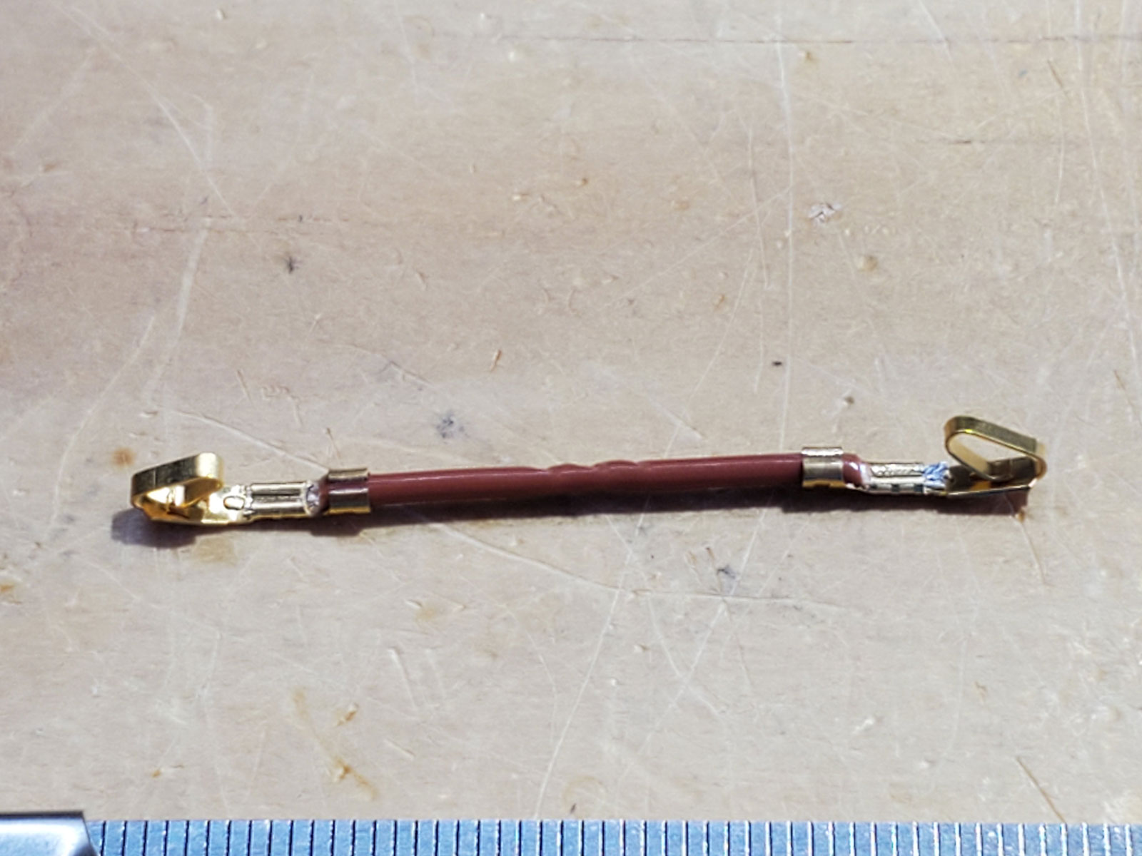
Anyway … to make the shorting jumpers, I cut 1" wire lengths, then strip 1/8" off of each end. Then I crimp on the terminals. This is the result:
We’re not done yet, though. The way the crimp terminals work in the housings is that there is a small bent tab on the top of the terminal that “catches” a slot in the end of the housing. This allows you to push the terminal into the housing until this tab reaches the slot. The tab springs up into the slot, so that you can’t pull the terminal back out. (Use a very tiny screwdriver tip to press the tab down while pulling the wire/terminal back out, if necessary.)
In working with the crimp terminals, that tab often gets bent back down, flush with the crimp terminal, so it won’t “catch” when you push it into a housing. So, I take an X-acto knife to bend the tabs back up:
Finally, the smooth jaw needle nose pliers helps me to bend everything back into a straight line. Again, working with the IWISS crimping tool, the crimp terminal sometimes ends up getting bent and distorted. This will prevent a proper insertion into the housing. The wire and tops of the crimp terminal should be as straight as possible across the top (except the bent up tab):
The next step is to bend the wire in half and insert both crimp terminals into the housing:
Once all of the above procedures are established (and re-remembered), it goes very fast. These were all done in a little less than an hour:
Next, I test the jumpers for continuity (zero resistance), just to make certain:
Sorry if that was excruciating details about a tiny connector. I thought it important, though, to explain the correct way to do it. Once I start on the transformers, all the rules go out the window.
I find little details like that just as fascinating as everything else! Keep on keeping on Tom, and thanks!
So, here we go - the last thing before casework assembly!
As mentioned earlier, the rules for the Molex connectors go out the window when it comes to the power transformers. The reason is that even though the leads on the SumR toroids are 22ga, the insulation is 600V. So, the insulation is easily twice the diameter of the stranded wire bundle. A different technique with the Molex terminals and the crimper must be used.
Here’s a pic of one of the power transformers with the leads trimmed:
I am not a magician. There’s no way I would trim the leads on an expensive, custom-made power transformer without having developed a guide of some sort. What you see there is my cheat sheet for the entire T4 construction. On the left, I have all of the parts documented, along with their heights, and ordered in the sequence that they should be soldered into the PCB. Also in that list is the lead-bending lengths to be used with the red plastic lead bending guide (seen in the early posts) for resistors and diodes.
Here’s the section on the PT:

It’s quite a bit of information, but absolutely necessary to prevent ruining one of the power transformers. The first step, as mentioned above, is trimming the leads to those lengths in the far right column. Then the groupings of the windings guide me in what to use for the Molex housings:
Here’s a pic (sorry - slightly out of focus) of a crimped transformer lead:
Here’s a pic with the primary leads (4 plus a shield) completed with the crimp terminals:
Once you get into a rhythm doing this, it goes very, very fast - faster than soldering, if you can believe it. Almost the same amount of time is taken in cutting/stripping/tinning the leads if you solder. Then you have to apply the solder and wait for the melting and cooling. None of the soldering time is needed with the crimp terminals. Here’s a power transformer ready to plug into a PCB:
It’s also extremely important that Green (the shield) is at the top of the connector when plugged into the headers on the PCB! You can actually reverse the order Black to Orange or Orange to Black (same windings relationship, but reverse order), but Green has to be the first connection, always.
Being AC voltage and only two wire connections, the order with the HT leads and the LT leads makes no difference. Just make dang sure the red and yellow go in the LT housing and the blue and gray go into the HT housing! Mixing that up is a no-no!
A test fit into a PCB (no bottom plate to mount the transformer for the time being):
As stated, once in a rhythm with the cutters, strippers, and crimper, things go very, very fast. I finished the rest of the transformers in under a couple of hours:
Final casework assembly begins!
EDIT: Should’ve mentioned this earlier, but except for the voltage-setting jumpers, I use the Molex housings with rib wings and locking ramp. As also mentioned, it doesn’t really matter except for the 5-pin housing. The rib wings and locking ramp on the 5-pin connector strongly encourages that the transformer primaries won’t be reverse-connected.
This is like a serial or a Mini-Series for audio nerds. I’m loving every word and image, Tom. Thank you for sharing!!!
Starting with the casework … the first thing that has to be addressed is the thermal bar technology:
This can make assembly difficult, if not impossible - if you aren’t careful and don’t have a plan. However, after doing this for a while, I’ve developed a system. That system begins with attaching the completed PCB to the case bottom plate. The bottom plate is what you see most prominently in the pic above. All of those drilled holes are for three things:
To the left of the bottom plate is a sheet of Bergquist thermal pads. In most instances, these pads are sized for TO-220 power transistors and used between a heat sink and the transistor. The pads have an adhesive backing, are made of cloth fibers, and impregnated with a coating that flows as a highly viscous liquid/goo under heat. It maximizes the heat transfer without all the mess of a classic thermal grease.
Above the bottom plate, you can see several aluminum rectangular bars. These are the thermal bars used for heat transfer in the T4, one per amplifier. The white rectangles are 2mm thick ceramic insulators. At top right, there’s a jar of classic thermal grease (still needed for other things) and a bottle of screw thread Loctite. Just to the right of the Loctite are vertical LED holders. One of these is used in soldering the primary LED to the PCB. It goes just behind the XLR jack and is used to illuminate the ECP Audio logo on the amplifier top plate. Finally, there are some machine screws and high-temp fiber washers. These are used to attach the thermal bar to the PCB.
The first step is to apply Loctite to all of the thermal bar holes. These holes are threaded for the screws used to attach the thermal bar to the PCB:
Once that’s done, the Bergquist pads are peeled off the plastic sheet and applied to the ceramic insulators. The Bergquist pads are used here to remove concerns with the messiness of the thermal grease, which ends up everywhere, despite the strongest attempts to keep it controlled. The ceramic insulators are used for the primary interface between the PCB and the thermal bar. The heat sink pads on the PCB are actually flowing with 250+ Volts and any chance of errant thermal grease in this interface needs to be removed. Thus, the use of the Bergquist pads:
Once those are applied, the next step is apply thermal grease to the back side of the ceramic insulators and place them in their proper positions on the thermal bar:
The very next step is to place the thermal bar in the middle of the table (carefully!) and then hover the PCB over the bar until you get the holes lined up. We’ve already installed the standoffs under the tube sockets, IEC inlet, and choke. Because of the fact that the thermal bar with ceramic insulators is exactly the same height as the standoffs, you can place the PCB over the thermal bar/ceramic insulators so that the holes match up exactly and everything is stable. Then carefully, I screw in a couple of the thermal bar screws so that I know the bar won’t move. Then the rest of the screws can be installed and torqued down. The Loctite will cure over the next several days and the connection will become quite secure.
The threaded holes in the thermal bar are through-holes, so they’ll be used with the case bottom plate, just as if it was five more standoffs. Here’s the thermal bar fully attached.
Looking at the top of the PCB, you can see the five screws and high-temp washers, all in a row:
If you look closely at the near tube socket and the transistor to its right, you can see what I mean about the white thermal grease - it gets everywhere, no matter how careful you are! (It was since cleaned up.)
The next step to complete mounting the PCB to the bottom plate is to attach the remaining standoffs. There are four more mounting holes on the PCB that were not attached to anything. Standoffs are attached and screwed in at these holes. One is different than the rest, however:
All the standoffs are attached in this pic, ready for attachment to the bottom plate. Most important, additional thermal grease has been applied all along the bottom of the thermal bar. This ensures a good heat transfer between the thermal bar and the bottom plate:
Once the bottom plate is attached and the thermal bar screws are torqued in place, top and bottom, we can inspect the thermal bar interface between PCB and bottom plate:
And a top view of the entire PCB/bottom plate assembly, ready for the front plate, back plate and sides:
Front plate(s) and back plate are next!
While casework assembly has begun in earnest, I’d like to take a small pause to thank our suppliers. Of course, the main person to thank for the casework and its design is dsavitsk:
Dsavitsk does all woodwork on his own. For the metal casework, however, he uses Front Panel Express. FPE is familiar to almost all of the DIY-ers in the audiophile culture. They are known for great precision and quality. I’ve used them on a number of occasions myself and can absolutely confirm this. Plus, their Front Panel Design software (free!) is a top-notch way to design casework and specify how to cut, punch, machine and finish the metal. If any of you have need for a unique casework design that can’t be met by the stock Hammond, Lansing, Box Enclosures, Context, etc. - FPE is a great choice.
There are some drawbacks with FPE, however, when it related to the T4:
The first and second item was a show-stopper for me. The brush finish is a straightforward process, but it has to be done with commercial machines or else the consistency is ruined. As for anodizing after machining, anyone who’s seen the bare metal edges on tube holes in casework understands the issue. Even though this is how Hammond machines and anodizing their cases (as used on the Starving Student that I sold for many years), it looks like poo. Look at the photo above and imagine a shiny, bare metal circle around those tubes and you understand - it kills the looks.
As it turned out, Dsavitsk would have the metal cut at FPE, then send it out to a friend who would brush finish and then anodize. When he received it back, Dsavitsk would add the laser etching himself. This was not possible for me. So, I started searching. I figured that Atlanta was a large enough city that we should have similar services to FPE somewhere. I had already been using a local anodizer and laser etcher for many years that did world-class quality work. (I have experience with an anodizer who did not!) Both had done excellent work previously on Beezar Audio’s DoodleBug, among other products:
That anodizing is provided by Metal Finishers of Atlanta. The laser-etching is provided by Laser Tech Atlanta. Both firms have done excellent work for me for almost a decade, now. I used to live only a couple of miles from Metal Finishers of Atlanta, so it was very, very convenient. Both services are true crafts, almost artwork. If you look at Laser Tech Atlanta’s website, you’ll see some fine examples of actual art and why I say that:
Anodizing is similar: the process is well known and documented, but the actual process details are more experience and judgment than anything else. The type of metal cleaning used, the method of clamping/mounting, and how long to leave the article in each tank during the process, are all variable tasks that can result in huge differences in quality.
Similarly, laser etching not only involves preparation of the artwork, but knowing the various materials and finishes and how to vary the etching settings variables that are necessary to have a design “pop” from the overall finish. It even takes first hand knowledge and experience of the anodizer in the depth of anodizing, etc. Most important - anodizing can actually be done over if it turns out bad, but laser etching cannot. It essentially ruins the metal, if it’s not done right. When you’ve invested several $ thousands in the metal work, failures in anodizing or laser etching are not desirable prospects - to say the least! (I’ve had it happen, unfortunately!!)
So, all that was in my mind while searching for a solution for the metal. I had to find someone who could precision cut, punch, and brush-finish aluminum to an equal quality of Front Panel Express. Then, I’d have to have it anodized and laser-etched, but at least with those two services - I already had the solution.
After flirting with a number of machinists (my own ignorance), one of them said what I really needed was sheet metal work. Having been familiar with the HVAC industry for many years, “sheet metal work” meant bending thin gauge galvanized steel and assembling it into ductwork with very rough, self-tapping screws:

No! That isn’t what I wanted. Yet, another machinist I contacted persisted: he said I needed to look at Swift Atlanta. So, I did.
The first thing I did was call them up and ask if they could machine metal plate and also brush-finish it. By that time, I had actually looked up the actual machines used to brush-finish (Time-Saver) and asked them if they had them - they did! Next thing I knew, they had invited me to their factory for a tour! Even though I had worked for Lockheed in my early career for 15 years, I was impressed with their operation! Giant Mitsubishi laser cutters, presses, Time Saver belt sanders (brush-finishers), CNC press brakes, etc., etc. They did clear anodizing and silk-screening (as good as I’ve ever seen), but no black anodizing or laser etching. I asked what they did if someone wanted black anodizing and laser-etching: their reply was that they used Metal Finishers of Atlanta and Laser Tech Atlanta ! The same people I used! They also stated that they’d handle the entire operation and quality control - including the outside services!
Speaking of the HVAC industry, Swift Atlanta does all of Automated Logic’s casework:
I had several more meetings with them, showing them the T4 finished prototype and letting them have a look at it, while I produced an entire set of CAD drawings for them. This was a lot of work. Dsavitsk had done the initial work in Front Panel Designer for FPE, but as convenient as their software was, it was not commercial/industrial CAD. I had done this in the past with Lansing on the Millett MiniMAX, Hammond Mfg with the Starving Student, PupDAC, and DoodleBug, and with Context Engineering on the original Torpedo. So while a lot of work, it was something I had done before. Here’s a couple of examples of the drawings that I produced:
Anyway - I highly recommend Swift Atlanta (and the other two processors) for anyone interested in some high-level casework. My experience with Swift Atlanta was one of the nicest - if not THE nicest - I’ve ever had with a supplier. They even sent me a Christmas card:

Great people! I just thought some of you would like to know the many people who helped make the T4 possible. It’s not just me and Dsavitsk!
Well, back to assembling these things!
Dsavitsk’s puzzle box design means that attachment points are all hidden, where possible. The bottom plate and rear back plate are exceptions, but even there, low head profile screws are used. For hidden attachments, special under-cut 82-degree, flat-head screws are used, with 100-degree counter-sunk holes. This results in an absolutely flush (or greater than flush) finish at all attachment points. These special screws are actually visible on the T4 lid, because a tube amplifier has to be constructed to allow changing out the tubes. Elsewhere, they are completely hidden - either with wood or with the large and heavy front plate. These screws are also used on the XLR jack, to keep its attachment point completely hidden.
What allows the screw attachments of the various metal plates are threaded mounting brackets:

The brackets look square, but they are not - being offset by about 1 millimeter. Every ECP Audio casework design uses these brackets to attach the metal sides, top and bottom of the “box.”
Hopefully, I’m not revealing too much here, but I thought an explanation was in order. It still takes quite a learning process on the best order of assembly. I have one for the T4, but it is not consistent with other ECP Audio casework designs. In fact, Dsavitsk has mentioned to me that he has designed casework that he was almost unable to assemble: “painting” himself into a corner on more than one occasion during assembly.
With the T4, as you have seen - I start with the bottom plate. Everything keys off of that. The next step is to attach the back plate, then the false front plate. The sides are next, then the lid. Sounds simple, but it really isn’t. I begin by attaching the metal brackets to the various plates. Back plates are here:
Also note the purple junk on all of the screws/brackets. This is Loctite that is applied and allowed to soak down into the threads for a day or two. The excess is then wiped off. It provides some “stickiness” to the screw joint. Otherwise, these brackets will spin like prop blades on the screws when just slightly loosened.
Here are the back plates and front plates ready for attachment to the amps (by screwing to the bottom plate):
And the side plates’ preparation also begins:
Let’s look a bit closer at how I attach these brackets:
Here’s the back plate, all propped up:
Here’s a similar look at the false front plate:
In the background and foreground, you can see all the other plates for the 6 amps arrayed around the table top with their brackets attached. Here’s a look at all of them:
So, these have cooked for a day or two, the excess Loctite soaked up with paper towels and assembly begins! Here’s an amplifier assembly with the front plate and rear plate attached:
Here’s the front plate attached:
A task missed earlier, the rubber bumpers were applied to keep the screw heads from scraping everything while moving the amplifier assemblies around:
In this pic, I placed the side plates in trial position. You can see how they will line up with the corner attachments to the other plates. Keep in mind that they are also completely flush on the outside. The three holes along the side plate centerline are for attaching the wood sides from the inside. Again, no attachment points will be visible from the outside, once completely assembled:
Here are some closer looks at the corner joints, including the metal-to-metal attachment for grounding:
I prefer to attach the wood sides to the metal side plates, before assembling them to the rest of the amp. That’s up next!
Speaking of the wood sides, let’s take a closer look at the wood and Dsavitsk’s workshop.
The wood used on the T4 is Sapele. The Wood Database states the following (quoted directly):
Color/Appearance
Heartwood is a golden to dark reddish brown. Color tends to darken with age. Besides the common ribbon pattern seen on quartersawn boards, Sapele is also known for a wide variety of other figured grain patterns, such as: pommele, quilted, mottled, wavy, beeswing, and fiddleback.
Grain/Texture
Grain is interlocked, and sometimes wavy. Fine uniform texture and good natural luster.
Common Uses
Veneer, plywood, furniture, cabinetry, flooring, boatbuilding, musical instruments , turned objects, and other small wooden specialty items. [my emphasis on musical instruments - TomB]
Comments
Sapele is a commonly exported and economically important African wood species. It’s sold both in lumber and veneer form. It is occasionally used as a substitute for Genuine Mahogany, and is sometimes referred to as “Sapele Mahogany.” Technically, the two genera that are commonly associated with mahogany are Swietenia and Khaya, while Sapele is in the Entandrophragma genus, but all three are included in the broader Meliaceae family, so comparisons to true mahogany may not be too far fetched.
Usually pronounced (sah-PELL-ey) or (sah-PEEL-ey).
This image, IMHO, is a good representation of the finished appearance:
Those of you with some experience with gemstones might note a tendency toward a brown cat’s eye gemstone appearance - very nice!
This is part of Dsavitsk’s workshop, with a plank of Sapele propped up on his very nice looking jointer/planer:
Preparing to rip on the also fine looking table saw:
Sapele ripped into the proper widths:
Notice the precision of Dsavitsk’s cuts:
And the Sapele T4 sides trimmed to length, rabbet joint cut, and ready for finishing:
Finally, clamped together ready for final sanding/finishing:
Dsavitsk typically uses a very conservative oil finish, several coats. Each coat is rubbed on, allowed to cure for a day, then rubbed off and another coat applied.
P.S. Just a side note about Dsavitsk’s wood working - you can actually find examples of his work, outside of the headphone culture, at Pickett Furniture in Brooklyn, NY:

That record player cabinet!!!


I want a jointer that big. Also want a Sawstop tablesaw of any kind.
Doug does good work!
Such beautiful work.
And with sound to match, a definite work of art.
I want one. 
Take my money!
LOL
Seriously, I am interested 
My apologies on some misattribution. Dsavitsk had shown me the pieces from Pickett furniture before, but he says he did the electronics and metal chasis work in the console and guitar amplifier, not the specific woodwork.
Pickett Furniture made some of Dsavitsk’s early casework, until Dsavitsk learned the techniques and started doing the woodwork himself.